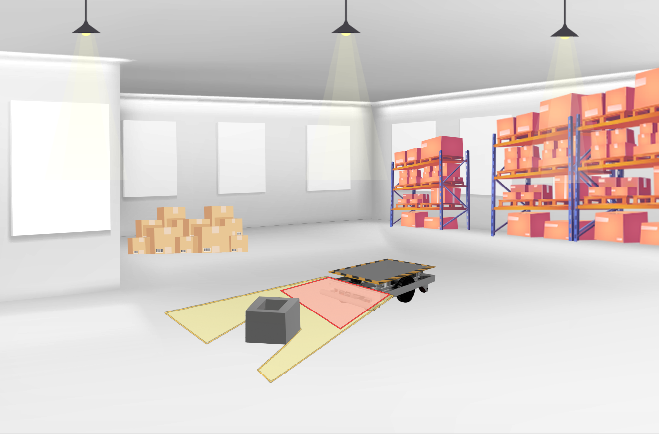
In the field of automated vehicles, finding a reliable and cost-effective obstruction detection system is crucial. This article follows our journey of searching for the ideal solution. Most modern AGV's use LIDAR but to save on costs we explored other options to start with but in the end went with a low cost Lidar due to reliable readings and ease of use. We started with ultrasonic distance sensors, explored time-of-flight infrared sensors, and ultimately discovered the potential of a cheap 2D LiDAR.
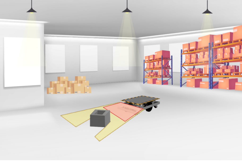
Simply put, ultrasonic sensors work based on the principle of sound waves. These sensors emit a high-frequency sound wave, typically beyond the range of human hearing, and then they measure the time it takes for the sound wave to bounce back after hitting an object. The information gathered from this process helps calculate the distance between the sensor and the object.
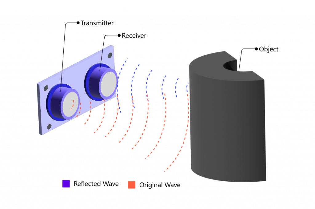
In the initial stages of our research, we opted for a range of ultrasonic distance sensors due to their affordability and reputation for reliability in distance measurement. We experimented with both generic ultrasonic distance sensor modules and car parking sensors, which operate on a similar principle. However, we discovered a significant limitation with these ultrasonic sensor arrays—the presence of a substantial blind spot between the sensors, making them unreliable in detecting objects with smaller widths. Additionally, when the vehicle was in motion at higher speeds or navigating corners, false triggers were observed, further compromising the accuracy of the system as an obstruction sensor for our automated guided vehicle (AGV). Consequently, we concluded that the output of this particular system was unsuitable and unreliable for our intended purpose.
Time-of-Flight (ToF) infrared sensors operate by emitting a burst of infrared light towards an object and measuring the time it takes for the light to bounce back to the sensor. This time interval, known as "time of flight," is directly related to the distance between the sensor and the object. By using the speed of light as a constant, the sensor calculates the distance accurately. Multiple measurements are often taken for improved precision. The sensor then processes this data and provides it as an output signal. ToF infrared sensors find applications in distance measurement, object detection, and gesture recognition in fields such as robotics, consumer electronics, automotive safety, and industrial automation.
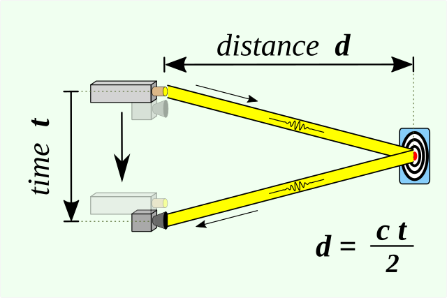
The infrared (IR)-based system for distance measurement was generally found to be unreliable due to several factors. One of the main issues was the interference caused by ambient IR radiation from sources such as sunlight and certain types of lamps. Additionally, the accuracy of distance measurement using IR technology heavily relied on the reflectivity of the object being measured, which posed limitations.
However, our search led us to a device from Texas Instruments called OPT3101. This IC proved to be a game-changer as it offered a Time-of-Flight (ToF)-based long-range proximity and distance sensor analog front end (AFE). Unlike the disadvantages of traditional IR-based systems, this IC had built-in features such as ambient and sunlight rejection, and ensuring accurate distance measurement regardless of the object's reflectivity. Moreover, it had a sample rate of up to 4 kHz and supported three transmitter channels, expanding the angle coverage and making it an excellent choice for our specific requirements.
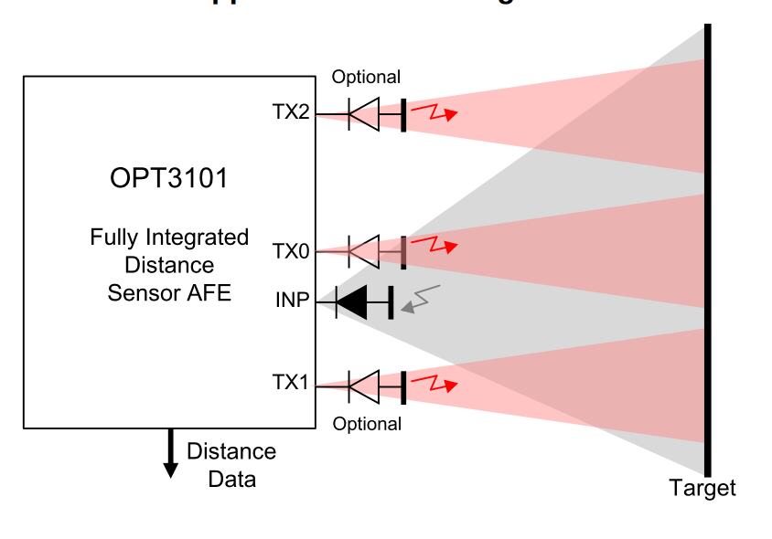
To implement this technology, we utilized a development board that incorporated the OPT3101 IC for obstruction detection in our AGV. However, we encountered challenges in calibrating and operating it reliably. The device had numerous variables to consider, and the default output tended to be noisy. As a result, designing a custom board and fine-tuning all the parameters for different conditions became a substantial undertaking in itself.
LiDAR (Light Detection and Ranging) technology uses laser pulses to measure distances and create detailed 2D or 3D maps of objects and environments. By emitting laser beams and analyzing the reflected light, LiDAR systems calculate the time it takes for the light to bounce back, allowing for precise distance measurements. With advancements in technology, LiDAR systems have become more compact, and affordable, It is widely used in various industries, including robotics, autonomous vehicles, and mapping.
During our search for an affordable and reliable solution, we were fortunate to come across the LD-14P 2D LiDAR developed by LD Robotics. This impressive LiDAR system not only fits within our budget but also offer exceptional features. It boasted a scanning range of 360°, allowing for comprehensive coverage, and could perform 4,000 distance measurements per second. Additionally, it had a scanning range of 0.1-8 meters and operated at a default scanning frequency of 6 Hz.
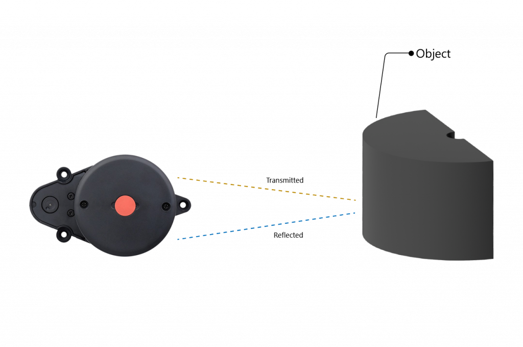
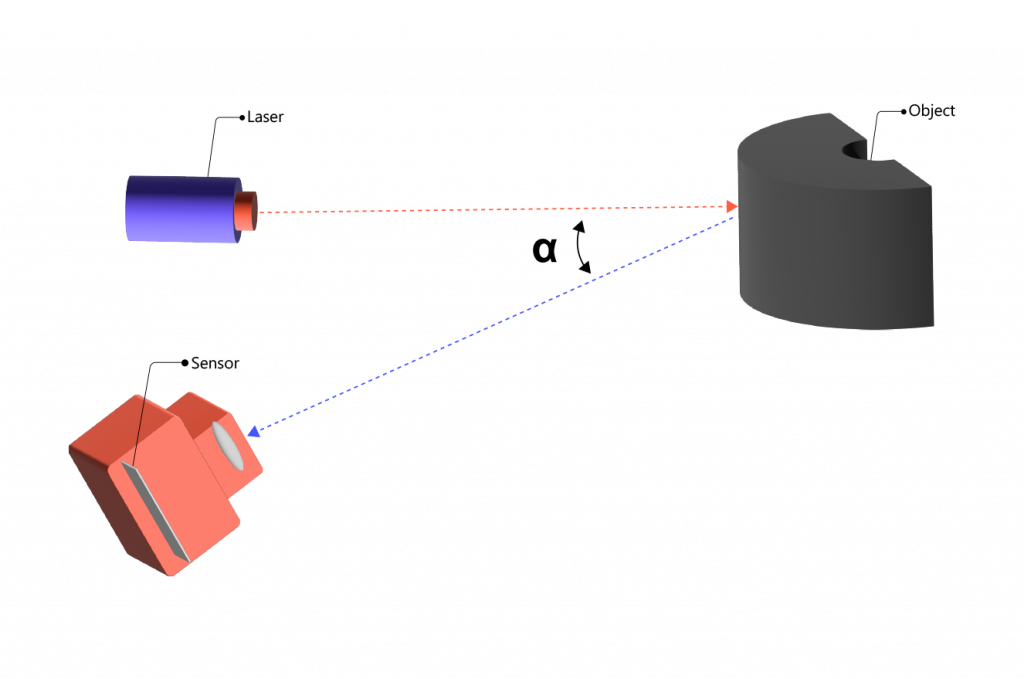
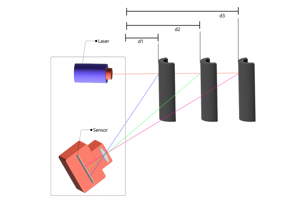
Operating on the principle of Triangulation, the LD-14P utilizes an infrared laser transmitter, a receiver, and a rotating plate with specialized optics. Through Triangulation measurement technology, a laser spot is projected onto the target object. The reflected light then reaches the receiving element at an angle determined by the distance. By emitting an infrared laser from a fixed angle and calculating the precise distance based on the triangle relationship formed between the laser, target object, and receiving unit, the LD-14P provides accurate distance measurements.
This LiDAR system proved highly effective in meeting our obstruction detection requirements. To simplify its integration, we developed an Arduino library that facilitated seamless communication with the LD-14P device. By employing a polar coordinate system, the library accurately detects objects within the rectangular area directly in front of the LiDAR device, allowing for precise obstacle identification and avoidance.
Now, let's learn how to connect and use this LiDAR with our beloved Arduino.
In this example, we would be using an ESP32 with Arduino IDE, but the code will be the same for an Arduino UNO also. The LD14P LiDAR module has four pins, which are as follows:
| No. | Function | Type | Decription |
|---|---|---|---|
| 1 | PWR/RX | Input | External speed control/Radar data input |
| 2 | GND | Power | Negative pole of power supply |
| 3 | TX | Output | Radar data output |
| 4 | VCC | Power | Positive pole of power supply |
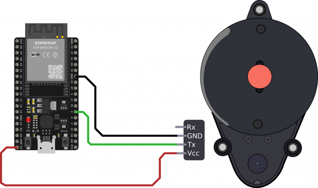
Once you power up the device, the module will begin spinning and sending data continuously through the transmit pin Tx. By default, the motor spins at a rate of 6 Hz. If you'd like to adjust this speed, you can use the Rx pin. Sending a Pulse Width Modulation (PWM) signal to the Rx pin allows you to control the speed from 2Hz to 8Hz. However, for this demonstration, we'll stick with the default 6Hz setting.
To set up the connection between the LD14P LiDAR module and the ESP32, follow these steps:
By configuring the ESP32 to read data from the connected GPIO pin using Serial.read() you'll be able to capture and interpret the information transmitted by the LD14P LiDAR module.
The data sent by the LiDAR follows a specific protocol, illustrated in the data packet format below:

Let's break down the components of this data packet:
Start character: This is 1 byte in length and holds a fixed value of 0x54. It indicates the beginning of the packet.
VerLen: This is 1 byte in length. The upper three bits designate the frame type, always fixed at 1. The lower five bits indicate the number of measurement points in a packet, set to 12 (0x2C) in this case.
Radar speed: This is 2 bytes in length and is measured in degrees per second.
Start angle: This is 2 bytes in length, measured in 0.01 degrees.
Data: Each measurement data is 3 bytes in length. More details about this will follow.
End angle: This is 2 bytes in length, measured in 0.01 degrees.
Timestamp: This is 2 bytes in length, measured in milliseconds. The maximum value is 30000, after which it resets.
CRC checksum: This is a checksum of all the previous data for verification.
By decoding this data packet, you can extract information about measurements taken by LiDAR.
The signal strength value shows how strongly the light reflects off an object. If the reflection is strong, the signal strength value is higher. If it's weak, the value is lower.
The angle for each measurement point is determined by smoothly connecting the starting and ending angles.
This is done using a simple calculation:
Find the step by dividing the difference between the end angle and start angle by one less than the number of measurement points in the packet:
step = (end_angle - start_angle) / (len - 1)Calculate the angle for each point using this formula:
angle = start_angle + step * iHere, "len" is the count of measurement points in the packet, and "i" ranges from 0 to len-1. This formula ensures that the angles are evenly distributed between the starting and ending angles.
Seems a bit complex? No worries! we've got your back! We've developed a library that simplifies the process. This library efficiently extracts all the crucial information from the data packet and identifies if there's an obstruction in your way. With this at your disposal, you can seamlessly integrate the LD14P LiDAR module into your project for obstruction detection without hassle.
(GitHub link to the Library)(not uploaded )
To install the library provided above in the Arduino IDE, follow these simple steps:
#include <LD14_P.h> to include the library's header file.That's it! You've successfully installed the library. You can now use the functions and features provided by the library to work with the LD14P LiDAR module in your Arduino projects.
Let's take a look at an example code.
#include "LD14_P.h"
#define  RXD2  5
#define  TXD2  4

#define  TRIGGER_PIN  LED_BUILTIN

LD14_P  lidar;
void  setup() {
  pinMode(TRIGGER_PIN, OUTPUT);
  digitalWrite(TRIGGER_PIN, HIGH);
  Serial.begin(115200);
  Serial2.begin(230400, SERIAL_8N1, RXD2, TXD2);
}

unsigned  long  triggerTime  =  0;
bool  triggered  =  false;

void  loop() {
  if(lidar.update()){
    if(lidar.checkCollisionRect(550, 500, 2)){
      triggerTime  =  millis();
      triggered  =  true;
    }
    else{
      if(millis() -  triggerTime  >  400){
        triggered  =  false;
      }
      else{
        triggered  =  true;
      }
    }
  }
  digitalWrite(TRIGGER_PIN, !triggered);
}
Initializing the LiDAR
Create an instance of the LD14_P class, which we've named lidar.
#include
"LD14_P.h"
LD14_P lidar;
Setting Up Communication
Configure the communication pins for the LD14P LiDAR. In this example, we use pins 47 and 48 for the RX and TX pins respectively.
#define RXD2 47
#define TXD2 48
void setup() {
  Serial.begin(115200); // Initialize Serial Monitor
  Serial2.begin(230400, SERIAL_8N1, RXD2, TXD2); // Initialize Serial2 for LiDAR communication
}
Handling Obstacle Detection
In the loop() function, we continuously fetch the LiDAR data using lidar.update() function
If a collision is detected in the rectangular area in front of the LiDAR (specified by lidar.checkCollisionRect()), we set triggerTime and triggered to true.
void loop() {
  if(lidar.update()){
    if(lidar.checkCollisionRect(550, 500, 2)){
      triggerTime = millis();
      triggered = true;
    }else{
      if(millis() - triggerTime > 400){
        triggered = false;
      }else{
        triggered = true;
      }
    }
  }
  digitalWrite(TRIGGER_PIN, !triggered); // Turn on the alert if an obstacle is detected
}
This example demonstrates how to use the LD14_P library to handle obstacle detection using the LD14P LiDAR module. You can modify the trigger conditions and the behaviour of the alert based on your specific project requirements.
Connect the lidar to the ESP32 and upload the provided code. Position the lidar in an open area and introduce an object within the defined region. You'll notice that the LED on the ESP32 will illuminate upon sensing an obstruction. Now, leverage this setup to activate an alarm, halt a robot, or even initiate a change in direction to avoid any detected obstacles.
(images of the project)
Our adventure in finding the right obstacle detection system for our Automated Guided Vehicle (AGV) was like exploring different paths. We began with ultrasonic sensors, but they had spots where they couldn't see and sometimes got things wrong. Time-of-Flight infrared sensors seemed cool, but they were tricky to set up and sometimes gave noisy results. The OPT3101 AFE IC was complex, with many things to handle. But then, LiDAR shone its light. We found the LD14P LiDAR from LD Robotics—a budget-friendly choice that also worked well. With the Arduino example and the library, we learned to understand the data it gave, and we could spot obstacles accurately. So, here we are, inviting you to use this tech for your own projects. Imagine a future where paths are clear, obstacles are seen ahead of time, and innovation takes you places you've never been before.
